N-bed development
From emboxit
- Board reviews moved there: n-bed review
Contents
UART
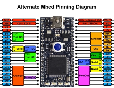
...Andy Kirkham's Alternative Mbed Pinout, which allows for using the three UART's and both SPI's.
I really think this alternative pinout should be included in every pinout post along with the standard pinout.
<cpp>
- include "mbed.h"
DigitalOut myled(LED1); Serial pc(USBTX, USBRX);
void RS485_Init(void); void RS485_SendChar(unsigned char data); void RS485_SendText(char *pString);
extern const unsigned int BRLookUp[][3];
void RS485_Init(unsigned int iBR, unsigned int iPCLK)
{
/* ===================================================================
   routine:    RS485_Init
   purpose:    Sets all required parameters for UART1 as RS485
               using following signals:

               mbed | LPC1768 | function
               -----+---------+---------
               P21  | P2[5]   | DTR - '1' for TX
               P25  | P2[1]   | RX
               P26  | P2[0]   | TX

   parameters: <iBR>        Desired baudrate
               <iPCLK>      Current peripheral clock in Hz
                            (mbed standard is 24000000)
   date:       2011-11-21
   author:     Stefan Guenther | Elektronikladen
   co-author:
   notes:      Calculation of baudrate based on NXP's algorithm in
               the LPC17xx manual, Fig. 50 on page 334.

                                       PCLK
               baud = ---------------------------------------
                      16*(256*DLM+DLL)*(1+(DivAddVal/MulVal))
 -------------------------------------------------------------------*/

   unsigned int iDL, iFR, iOffset, x;
   unsigned char cDLM, cDLL, cMULVAL, cDIVADDVAL;

   iDL = iPCLK/(16*iBR);

   if(iDL*16*iBR==iPCLK)           //iDL is an even number
   {
       cDIVADDVAL = 0;
       cMULVAL    = 1;
       cDLM       = 0;
       cDLL       = 0;
   } else                          //iDL is an odd number
   {
       iOffset=0;
       do                          //change iFR until it's value is within 1.1 .. 1.9 range
       {
           iOffset+=100;
           iFR = 1005+iOffset;
           iDL=iPCLK/(0.016*iBR*iFR);
           iFR=iPCLK/(0.016*iBR*iDL);
       } while((iFR>1900) || (iFR<1100));

       //iFR is now correctly calculated!

       cDLM        = (iDL>>8);
       cDLL        = iDL;
       x = 0;

       do                          //use lookup table to find values for DIVADDVAL and MULVAL
       {
           x++;
       } while(BRLookUp[x][0]<iFR);

       cDIVADDVAL = BRLookUp[x][1];
       cMULVAL    = BRLookUp[x][2];
   }
   //Now, all necessary values are calculated for the desired baudrate according to
   //the current PCLK frequency. These values (cDLM, cDLL, cDIVADDVAL and cMULVAL)
   //now are used to configure UART1 for RS485 communication.

   LPC_PINCON->PINSEL4    |= 0x80A;        //RXD1, TXD1, DTR1
   LPC_SC->PCONP          |= (1<<4);       //Power on UART1
   //LPC_SC->PCLKSEL                       //clock default is /4, we keep this
   LPC_UART1->LCR          = 0x83;         //sets DLAB; 8bit,1stopbit
   LPC_UART1->DLL          = cDLL;         //UART Divisor Latch LSB
   LPC_UART1->FDR          = cDIVADDVAL;   //DivAddVal
   LPC_UART1->FDR         |= (cMULVAL<<4); //MulVal
   LPC_UART1->DLM          = cDLM;         //UART Divisor Latch MSB
   LPC_UART1->LCR         &=~(1<<7);       //clears DLAB
   LPC_UART1->RS485CTRL   &=~(1<<1);       //Receiver enabled
   LPC_UART1->RS485CTRL   &=~(1<<2);       //AAD disabled
   LPC_UART1->RS485CTRL   |= (1<<3);       //DTR used for direction control
   LPC_UART1->RS485CTRL   |= (1<<4);       //direction control enabled
   LPC_UART1->RS485CTRL   |= (1<<5);       //DTR=1 when transmitting
   //LPC_UART1->IER |= 1;                  //RBR IRQ enable
   //LPC_UART1->TER &= ~0x80;              //!TXEN - disable transmitter, enable receiver
   //NVIC_EnableIRQ(UART1_IRQn);           //set up CM3 NVIC to process UART1 IRQs
   RS485_SendText("\nRS485 communication port setup succesful!\n\n");
}
void RS485_SendChar(unsigned char data) {
   LPC_UART1->TER |= 0x80;                 //enable transmitter
   while (!(LPC_UART1->LSR & 0x20));       //wait for UART1 to be ready - !!could lock up system!!
   LPC_UART1->THR=data;                    //write to THR register triggers transmission
}
void RS485_SendText(char *pString) {
   char *pText;                            //initialize pointer
   pText=(char *)pString;                  //set pointer to first character
   while(*pText!=0x00) {                   //0x00 marks end of text string
       RS485_SendChar(*pText);             //send each character seperately
       *pText++;                           //move pointer to next character
   }
}
int main() {
   RS485_Init(115200, 24000000);           //setup RS485 communication with 115200baud

   while(1) {
       myled = 1;
       wait(0.2);
       myled = 0;
       wait(0.2);
   }
}
/* ===================================================================
   table:      BRLookUp
   purpose:    provides settings for UART configuration (baudrate)
   date:       2011-02-04
   author:     Stefan Guenther | Elektronikladen
   source:     NXP's user manual for the LPC17xx (UM10360), Page 335
 -------------------------------------------------------------------*/
const unsigned int BRLookUp[72][3] = {
   1000,     0,  1,
   1067,    1,    15,
   1071,    1,    14,
   1077,    1,    13,
   1083,    1,    12,
   1091,    1,    11,
   1100,    1,    9,
   1125,    1,    8,
   1133,    2,    15,
   1143,    1,    7,
   1154,    2,    13,
   1167,    1,    6,
   1182,    2,    11,
   1200,    1,    5,
   1214,    3,    14,
   1222,    2,    9,
   1231,    3,    13,
   1250,    1,    4,
   1267,    4,    15,
   1273,    3,    11,
   1286,    2,    7,
   1300,    3,    10,
   1308,    4,    13,
   1333,    1,    3,
   1357,    5,    14,
   1364,    4,    11,
   1375,    3,    8,
   1385,    5,    13,
   1400,    2,    5,
   1417,    5,    12,
   1429,    3,    7,
   1444,    4,    9,
   1455,    5,    11,
   1462,    6,    13,
   1467,    7,    15,
   1500,    1,    2,
   1533,    8,    15,
   1538,    7,    13,
   1545,    6,    11,
   1556,    5,    9,
   1571,    4,    7,
   1583,    7,    12,
   1600,    3,    5,
   1615,    8,    13,
   1625,    5,    8,
   1636,    7,    11,
   1643,    9,    14,
   1667,    2,    3,
   1692,    9,    13,
   1700,    7,    10,
   1714,    5,    7,
   1727,    8,    11,
   1733,    11,    15,
   1750,    3,    4,
   1769,    10,    13,
   1778,    7,    9,
   1786,    11,    14,
   1800,    4,    5,
   1818,    9,    11,
   1833,    5,    6,
   1846,    11,    13,
   1857,    6,    7,
   1867,    13,    15,
   1875,    7,    8,
   1889,    8,    9,
   1900,    9,  10,
   1909,    10,    11,
   1917,    11,    12,
   1923,    12,    13,
   1929,    13,    14,
   1933,    14,    15
};
</cpp>
GPIO
HOW TO SETUP OTHER mbed PINS AS UART:
LPC_PINCON->PINSEL4    |= 0x80A;        //RXD1, TXD1, DTR1
CAN bus
Ethernet
- mbed schematic pdf
- mbed Connect magjack and USB?
- magjack data
- MBED RJ45 Ethernet MagJack Breakout
- MOUSER ABRACON ASDMB-50.000MHZ-LC-T
- DIGIKEY ABRACON ASDMB-50.000MHZ-LC-T, at Digikey INCLUDES 3D MODEL
- What is RMII
So here is what the data sheets says for the DP83848J

X2 – Crystal Output : This pin is the primary clock reference output to connect to an external 25MHZ crystal. This pin must be left unconnected if an external CMOS oscillator clock is used.
You are using a CMOS oscillator ? If so its ok.

TX-CLK -
MII TRANSMIT CLOCK:
25 MHz Transmit clock output in 100
Mb/s mode or 2.5 MHz in 10 Mb/s mode derived from the 25 MHz
reference clock.
Unused in RMII mode. The device uses the X1 reference clock in-
put as the 50 MHz reference for both transmit and receive

RX-CLK -
MII RECEIVE CLOCK:
Provides the 25 MHz recovered receive
clocks for 100 Mb/s mode and 2.5 MHz for 10 Mb/s mode.
Unused in RMII mode. The device uses the X1 reference clock in-
put as the 50 MHz reference for both transmit and receive

I guess if in RMI mode leave unconnected.

Similar RXD2/3 and TXD2/3 are unconnected if in RMI mode this is ok I think.
mbed CMSIS-DAP
