Difference between revisions of "Project STM32F103C6 CAN"
From emboxit
m (1 revision) |
|
(No difference)
| |
Latest revision as of 16:51, 11 September 2015
Project STM32F103C6_CAN
- canALL_V2 boards connected on CAN-BUS network
- Software on
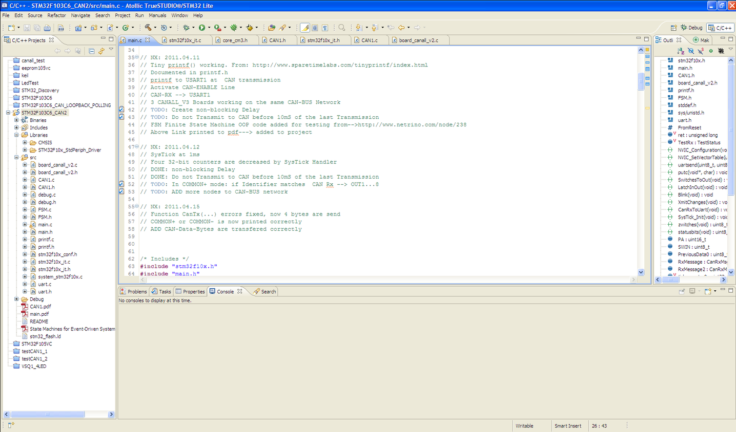
- Atollic TrueSTUDIO®/STM32 Lite, Built on Eclipse.
- Version: 2.0.1 Lite
- Build id: 20110128-1032
- Send to CAN only when an input is changed
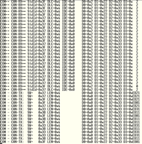
- All Receiving boards transmit to UART
- CAN-BUS can be monitored on PC Terminal Emulator
- On progress:
- Use board addressing to activate outputs from other board inputs
- // TODO: In COMMON+ mode: if Identifier matches CAN Rx --> OUT1...8
// NX: 2011.03.17
// FROM STM32F103C6_CAN_LOOPBACK_POLLING, FROM testCAN1_1 of ThanasisPolitis, after some effort
// testCAN1.c updated: Normal mode instead loopback, transmit only once, correct baud rate 125KHz (=8us)
// TODO: send to CAN every 10ms
// TODO: HOWTO define APB1 clock (now set to 36MHz) Try 8,16,24 MHz

// NX: 2011.03.30
//
// NX: 2011.04.6
// board.c,h renamed to board_canall_v2
// DSW6..1 now pull-up inputs as in canall_v2. (previous definition was for board FLO)

// NX: 2011.04.07
// DSW1..6 TO OUTPUTS 1-6
// TODO: SOLVE DSW6  NOT PULLED-UP

// NX: 2011.04.08
// DONE: SOLVE DSW6  NOT PULLED-UP, ...Had to enable AFIO clock
// IN1..8 Latched for COMMON+ (both jumpers RIGHT)
// IN1 and IN2 only Latched for COMMON- (both jumpers LEFT) IN3..8, do-nothing
// ONLY for COMMON-,  DSDW1...6 activate OUT3...8
// One led blinks at every main-loop
// The other led blinks when there is a change in the outputs OUT1..8
// Send a CAN transmission at every output change which contains OUT1...8
// TODO: Send DSW1...6 as Identifier, Send IOCOMLV Bit, Send FROM-RESET Bit
// TODO: CAN RX to UART for any Identifier
// TODO: In COMMON+ mode: if Identifier matches  CAN Rx --> OUT1...8
// TODO: Check Data Passed

// NX: 2011.04.09
// DONE: Send DSW1...6 as Identifier(whenever changes), Send IOCOMLV (BIT 1), Send FROM-RESET (BIT 0)
// Send FROM-RESET Bit
// UART function working, iprintf not working.

// NX: 2011.04.11
// Tiny printf() working. From: http://www.sparetimelabs.com/tinyprintf/index.html
// Documented in printf.h
// printf to USART1 at  CAN transmission
// Activate CAN-ENABLE Line
// CAN-RX --> USART1
// 3 CANALL_V3 Boards working on the same CAN-BUS Network
// TODO: Create non-blocking Delay
// TODO: Do not Transmit to CAN before 10mS of the last Transmission
// FSM Finite State Machine OOP code added for testing from-->http://www.netrino.com/node/238
// Above Link printed to pdf---> added to project

// NX: 2011.04.12
// SysTick at 1ms
// Four 32-bit counters are decreased by SysTick Handler
// DONE: non-blocking Delay
// DONE: Do not Transmit to CAN before 10mS of the last Transmission
// TODO: In COMMON+ mode: if Identifier matches  CAN Rx --> OUT1...8
// TODO: ADD more nodes to CAN-BUS network

// NX: 2011.04.15
// Function CanTx(...) errors fixed, now 4 bytes are send
// COMMON+ or COMMON- is now printed correctly
// ADD CAN-Data-Bytes are transfered correctly


/* Includes */
#include "stm32f10x.h"
#include "main.h"
#include "CAN1.h"
#include "board_canall_v2.h"
#include "printf.h"         	// NX: From: http://www.sparetimelabs.com/tinyprintf/index.html
#include "FSM.h"


// from main.c --> http://zrusavpt-eagle.googlecode.com/svn-history/r33/trunk/STM32/uart_vl_discovery/src/
#include <stddef.h>
//#include <stdio.h> 			// NX: made comment to avoid conflict with tiny-printf definitions
#include <sys/unistd.h>
// #include "stm32f10x.h"
// #include "STM32_Discovery.h"

// debug.c,h uart.c,h  Downloaded from-> http://zrusavpt-eagle.googlecode.com/svn-history/r33/trunk/STM32/uart_vl_discovery/src/
// #include "debug.h"
#include "uart.h"				// from-> http://zrusavpt-eagle.googlecode.com/svn-history/r33/trunk/STM32/uart_vl_discovery/src/


#define FromReset 0x01			// NX: BIT SET only at the beginning of main() for a single CAN transmission then is RESET


//	#define     __IO    volatile                  /*!< defines 'read / write' permissions   */
	__IO unsigned long ret = 0; /* for return of the interrupt handling */
	volatile TestStatus TestRx;


void NVIC_Configuration(void);
void NVIC_SetVectorTable(uint32_t NVIC_VectTab, uint32_t Offset);
void uartsend(uint8_t d0, uint8_t d1, uint8_t d2, uint8_t d3, uint8_t d4, uint8_t d5, uint8_t d6, uint8_t d7, uint8_t d8, uint8_t d9);
void putc ( void* p, char c);
void SwitchesToOut(void);
void LatchInOut(void);
void Blink(void);
void XmitChanges(void);
void CanRxToUart(void);
void SysTick_Init(void);

uint8_t zwitches(void);
uint8_t statusbits(void);

uint16_t PA;
uint8_t SWIN;
uint8_t PreviousData0;

CanRxMsg RxMessage;
CanRxMsg RxMessage2;

volatile uint32_t tick_counter0;
volatile uint32_t tick_counter1;
volatile uint32_t tick_counter2;
volatile uint32_t tick_counter3;

/*********************************************************************************/
//void Delay(vu32 nCount)
//{
//  for(; nCount != 0; nCount--);
//}

/**===========================================================================
**
**  Abstract: main program
**
**===========================================================================
*/
int main(void) {
//    Keyboard k;
//    KeyboardCtor(&k);
//    FsmInit((Fsm *)&k, 0);


	SystemInit(); //	Setup STM32 system (clock, PLL and Flash configuration)
	InitBoardCanall();
	InitializeUarts();
	init_printf(NULL,putc);

	SysTick_Init();

	CAN1_setup();
	CanTx(zwitches(),0x04,   FromReset,0x22,0x33,0x44);	// [Identifier,length,data1,data2,data2,data3]
	CanTxWait();

	while (1) {
		Blink();
		SwitchesToOut();
		LatchInOut();
		if (tick_counter0 == 0) XmitChanges();
		CanRxToUart();

//		KeyboardEvt ke;
//		printf("\nSignal<-");
//		ke.code = getc(stdin);
//		getc(stdin); /* discard '\n' */
//		switch (ke.code) {
//		case '^':
//			ke.super_.sig = SHIFT_DEPRESSED_SIG;
//			break;
//		case '6':
//			ke.super_.sig = SHIFT_RELEASED_SIG;
//			break;
//		case '.':
//			return 0; /* terminate the test */
//		default:
//			ke.super_.sig = ANY_KEY_SIG;
//			break;
//		}
//		FsmDispatch((Fsm *) &k, (Event *) &ke); /* dispatch */

	}//while(1) end
}//main end

uint8_t zwitches(void){
	uint8_t SW;
	SW = 1  * GPIO_ReadInputDataBit(GPIOB, GPIO_Pin_15)
	   + 2  * GPIO_ReadInputDataBit(GPIOB, GPIO_Pin_14)
	   + 4  * GPIO_ReadInputDataBit(GPIOB, GPIO_Pin_13)
	   + 8  * GPIO_ReadInputDataBit(GPIOB, GPIO_Pin_12)
	   + 16 * GPIO_ReadInputDataBit(GPIOB, GPIO_Pin_11)
	   + 32 * GPIO_ReadInputDataBit(GPIOB, GPIO_Pin_3);
	return SW;
}//uint8_t switches(void){

uint8_t statusbits(void){
	uint8_t BITS;
	BITS = 2  * GPIO_ReadInputDataBit(GPIOA, GPIO_Pin_8);		// NX: IOCOMLV line of Board
	return BITS;
}

void uartsend(uint8_t d0, uint8_t d1, uint8_t d2, uint8_t d3, uint8_t d4, uint8_t d5, uint8_t d6, uint8_t d7, uint8_t d8, uint8_t d9){
	USART_SendData(USART1, d0);
	while (USART_GetFlagStatus(USART1, USART_FLAG_TC) == RESET) {}
	USART_SendData(USART1, d1);
	while (USART_GetFlagStatus(USART1, USART_FLAG_TC) == RESET) {}
	USART_SendData(USART1, d2);
	while (USART_GetFlagStatus(USART1, USART_FLAG_TC) == RESET) {}
	USART_SendData(USART1, d3);
	while (USART_GetFlagStatus(USART1, USART_FLAG_TC) == RESET) {}
	USART_SendData(USART1, d4);
	while (USART_GetFlagStatus(USART1, USART_FLAG_TC) == RESET) {}
	USART_SendData(USART1, d5);
	while (USART_GetFlagStatus(USART1, USART_FLAG_TC) == RESET) {}
	USART_SendData(USART1, d6);
	while (USART_GetFlagStatus(USART1, USART_FLAG_TC) == RESET) {}
	USART_SendData(USART1, d7);
	while (USART_GetFlagStatus(USART1, USART_FLAG_TC) == RESET) {}
	USART_SendData(USART1, d8);
	while (USART_GetFlagStatus(USART1, USART_FLAG_TC) == RESET) {}
	USART_SendData(USART1, d9);
	while (USART_GetFlagStatus(USART1, USART_FLAG_TC) == RESET) {}
}

void putc ( void* p, char c)
	{
	while (USART_GetFlagStatus(USART1, USART_FLAG_TC) == RESET) {}
	USART_SendData(USART1, c);
	}

void SwitchesToOut(void){
	uint8_t inputDSW;
inputDSW = GPIO_ReadInputDataBit(GPIOB, GPIO_Pin_15);
if (inputDSW == 0)  {GPIO_SetBits(GPIOA, GPIO_Pin_2);}
	else {GPIO_ResetBits(GPIOA, GPIO_Pin_2);}
inputDSW = GPIO_ReadInputDataBit(GPIOB, GPIO_Pin_14);
if (inputDSW == 0)  {GPIO_SetBits(GPIOA, GPIO_Pin_3);}
	else {GPIO_ResetBits(GPIOA, GPIO_Pin_3);}
inputDSW = GPIO_ReadInputDataBit(GPIOB, GPIO_Pin_13);
if (inputDSW == 0)  {GPIO_SetBits(GPIOA, GPIO_Pin_4);}
	else {GPIO_ResetBits(GPIOA, GPIO_Pin_4);}
inputDSW = GPIO_ReadInputDataBit(GPIOB, GPIO_Pin_12);
if (inputDSW == 0)  {GPIO_SetBits(GPIOA, GPIO_Pin_5);}
	else {GPIO_ResetBits(GPIOA, GPIO_Pin_5);}
inputDSW = GPIO_ReadInputDataBit(GPIOB, GPIO_Pin_11);
if (inputDSW == 0)  {GPIO_SetBits(GPIOA, GPIO_Pin_6);}
	else {GPIO_ResetBits(GPIOA, GPIO_Pin_6);}
inputDSW = GPIO_ReadInputDataBit(GPIOB, GPIO_Pin_3);
if (inputDSW == 0)  {GPIO_SetBits(GPIOA, GPIO_Pin_7);}
	else {GPIO_ResetBits(GPIOA, GPIO_Pin_7);}
}//void SwitchesToOut(void){

void LatchInOut(void){
	uint8_t inputDSW;
	if (GPIO_ReadInputDataBit(GPIOA, GPIO_Pin_8) !=0){
		inputDSW = GPIO_ReadInputDataBit(GPIOB, GPIO_Pin_0);				// IN1
		if (inputDSW == 0)  {GPIO_SetBits(GPIOA, GPIO_Pin_0);}				// TO
			else {GPIO_ResetBits(GPIOA, GPIO_Pin_0);}						// OUT1
		inputDSW = GPIO_ReadInputDataBit(GPIOB, GPIO_Pin_1);				// IN2
		if (inputDSW == 0)  {GPIO_SetBits(GPIOA, GPIO_Pin_1);}				// TO
			else {GPIO_ResetBits(GPIOA, GPIO_Pin_1);}						// OUT2
		inputDSW = GPIO_ReadInputDataBit(GPIOB, GPIO_Pin_5);				// IN3
		if (inputDSW == 0)  {GPIO_SetBits(GPIOA, GPIO_Pin_2);}				// TO
			else {GPIO_ResetBits(GPIOA, GPIO_Pin_2);}						// OUT3
		inputDSW = GPIO_ReadInputDataBit(GPIOB, GPIO_Pin_8);				// IN4
		if (inputDSW == 0)  {GPIO_SetBits(GPIOA, GPIO_Pin_3);}				// TO
			else {GPIO_ResetBits(GPIOA, GPIO_Pin_3);}						// OUT4
		inputDSW = GPIO_ReadInputDataBit(GPIOB, GPIO_Pin_9);				// IN5
		if (inputDSW == 0)  {GPIO_SetBits(GPIOA, GPIO_Pin_4);}				// TO
			else {GPIO_ResetBits(GPIOA, GPIO_Pin_4);}						// OUT5
		inputDSW = GPIO_ReadInputDataBit(GPIOB, GPIO_Pin_10);				// IN6
		if (inputDSW == 0)  {GPIO_SetBits(GPIOA, GPIO_Pin_5);}				// TO
			else {GPIO_ResetBits(GPIOA, GPIO_Pin_5);}						// OUT6
		inputDSW = GPIO_ReadInputDataBit(GPIOC, GPIO_Pin_14);				// IN7
		if (inputDSW == 0)  {GPIO_SetBits(GPIOA, GPIO_Pin_6);}				// TO
			else {GPIO_ResetBits(GPIOA, GPIO_Pin_6);}						// OUT7
		inputDSW = GPIO_ReadInputDataBit(GPIOA, GPIO_Pin_15);				// IN8
		if (inputDSW == 0)  {GPIO_SetBits(GPIOA, GPIO_Pin_7);}				// TO
			else {GPIO_ResetBits(GPIOA, GPIO_Pin_7);}						// OUT8
		}// if end
		else {																	//COMMON- [JUMPERS BOTH LEFT]
			inputDSW = GPIO_ReadInputDataBit(GPIOB, GPIO_Pin_0);				// IN1
			if (inputDSW == 0)  {GPIO_SetBits(GPIOA, GPIO_Pin_0);}				// TO
				else {GPIO_ResetBits(GPIOA, GPIO_Pin_0);}						// OUT1
			inputDSW = GPIO_ReadInputDataBit(GPIOB, GPIO_Pin_1);				// IN2
			if (inputDSW == 0)  {GPIO_SetBits(GPIOA, GPIO_Pin_1);}				// TO
				else {GPIO_ResetBits(GPIOA, GPIO_Pin_1);}						// OUT2
		}//else end


}//void LatchInOut(){

void Blink(void){
	GPIO_SetBits(GPIOC, GPIO_Pin_13);
	//Delay((u32) 100000);
	GPIO_ResetBits(GPIOC, GPIO_Pin_13);
	//Delay((u32) 100000);
}//void Blink(void){

void XmitChanges(void){
	if ( (PA != GPIO_ReadOutputData(GPIOA)) | (SWIN != zwitches()) ){		// NX: If any of OUT1...8 changes
		GPIO_SetBits(GPIOC, GPIO_Pin_15);									// LED ON
		CanTx(zwitches(),0x04,   statusbits(),0x22,0x33,PA);				// [Identifier,length,data1,data2,data2,data3]
		CanTxWait();														// Transmit to CAN
		//Delay((u32) 100000);
		GPIO_ResetBits(GPIOC, GPIO_Pin_15);									// LED OF
		PA= GPIO_ReadOutputData(GPIOA);
		SWIN = zwitches();

		if ( (2 & statusbits()) !=0) {
			printf("COM++ ");
		}
		else {
			printf("COM - " );
		}

		printf("CAN-TX:  SW=   0x%X LEN=0x4            D0=0x%X D1=0x22 D2=0x33 D3=0x%X\n", zwitches(),statusbits(),PA);
		tick_counter0 = 10;		// Do Not Transmit before 10ms  passed from previous Transmission
	}//if ( (PA != ...
}//void XmitChanges(void){


void CanRxToUart(void){
	CAN_Receive(CAN1, CAN_FIFO0, &RxMessage);

	if (RxMessage.StdId != RxMessage2.StdId){
		if ( (2 & RxMessage.Data[0]) !=0) {
			printf("COM++ ");
		}
		else {
			printf("COM - " );
		}

		printf("CAN-RX** StdId=0x%X DLC=0x%X IDE=0x%X    D0=0x%X D1=0x%X D2=0x%X D3=0x  %X\n", RxMessage.StdId,RxMessage.DLC, RxMessage.IDE ,
														   RxMessage.Data[0],RxMessage.Data[1],RxMessage.Data[2],RxMessage.Data[3]);
		RxMessage2.StdId = RxMessage.StdId;

		RxMessage.StdId=0x00;
		RxMessage.IDE=CAN_ID_STD;
		RxMessage.DLC=0;
		RxMessage.Data[0]=0x00;
		RxMessage.Data[1]=0x00;
		RxMessage.Data[2]=0x00;
		RxMessage.Data[3]=0x00;
	}//if (RxMessage.StdId != RxMessage2.StdId){
}//void CanRxToUart(void){


void SysTick_Init(void)
{
	  SysTick->LOAD  = 0x2300;      // set reload register 0x2300 for 1ms
	  SysTick->VAL   =  0x2300;
//	  SysTick->CTRL |= SysTick_CTRL_CLKSOURCE;
	  SysTick->CTRL |= SysTick_CTRL_ENABLE;
	  SysTick->CTRL |= SysTick_CTRL_TICKINT;
}


/*
* @brief  Configures the NVIC and Vector Table base address.
* @param  None
* @retval None
*/
void NVIC_Configuration(void)
{
	NVIC_InitTypeDef NVIC_InitStructure;

/* Enable CAN1 RX0 interrupt IRQ channel */
#ifndef STM32F10X_CL
	NVIC_InitStructure.NVIC_IRQChannel = USB_LP_CAN1_RX0_IRQn;
#else
	NVIC_InitStructure.NVIC_IRQChannel = CAN1_RX0_IRQn;
#endif /* STM32F10X_CL*/
	NVIC_InitStructure.NVIC_IRQChannelPreemptionPriority = 0;
	NVIC_InitStructure.NVIC_IRQChannelSubPriority = 0;
	NVIC_InitStructure.NVIC_IRQChannelCmd = ENABLE;
	NVIC_Init(&NVIC_InitStructure);
}
- At every input change:
- change is transmitted to CAN
- Total STATUS of board is transmitted to UART
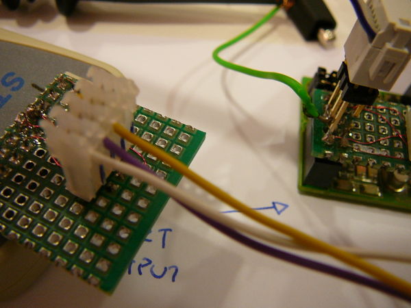
- Blue Channel CAN-BUS
- Purple Channel UART-TX
- ST-LINK to board
- UART to RS232 level converted board and then to PC serial port


