Difference between revisions of "ParkingMagneticSensor"
From emboxit
m (1 revision) |
|
(No difference)
| |
Latest revision as of 16:51, 11 September 2015
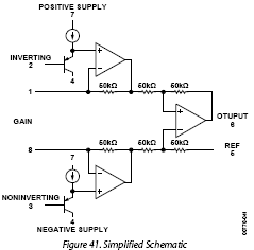
- AD623A Digikey $4.28@1pc $3.44@25pcs
- Analog Devices AD623 Single-Supply, Rail-to-Rail, Low Cost Instrumentation Amplifier datasheet
- 220 Ohm at AD623A Pins 1-8 is a GAIN close to 500
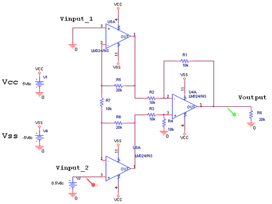
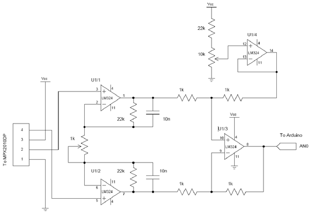
- LM324 instrumentation single supply edaboard Connect R4 to 2.5V
- LM324 Instr amplifierwater-tank-depth-sensor-schematic.pdf
- Laboratory 5: Instrumentation Amplifier
- lm324 Datasheet
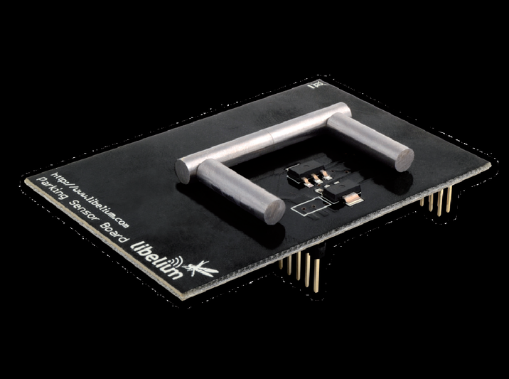
- FROM Libelium Smart Parking Board Technical Guide
2.2. Measurement Process
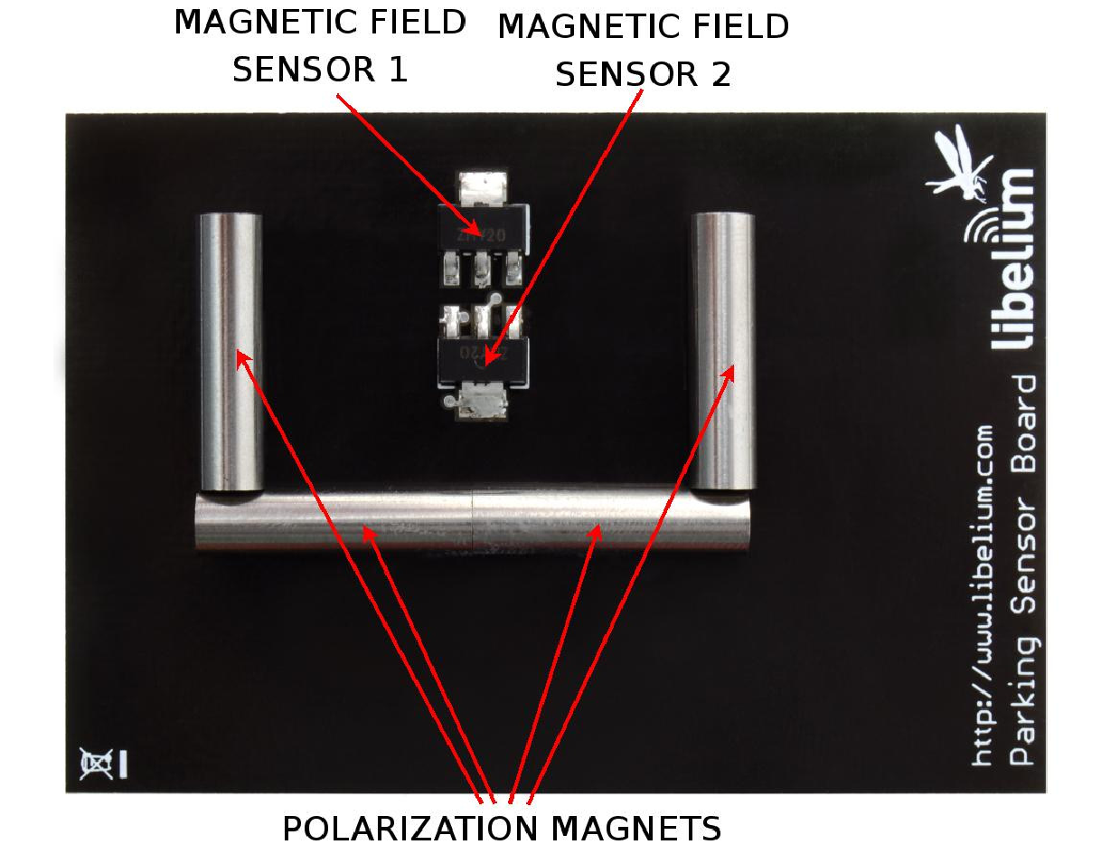
The ZMY20 sensor basically consists of a thin film of permalloy whose resistance is a function of the magnetic field through it
(intensity and orientation). This film is integrated in a Wheatstone bridge of resistance between 1.2kΩ and 2.2kΩ (typically 1.7kΩ),
thus between the two output terminals of the sensor we have a voltage in the order of the 20mV/V with a supply voltage of 5V.

In the final configuration two sensors in opposing orientation have been attached in order to improve the reliability of the device
and, to increase the stability of the two sensors,
Four small magnets have been placed in order to fix the magnetic field in the X axis (Hx),
minimizing the effect on the measurement of small variations of the magnetic field, such as those of the earth’s magnetic field.
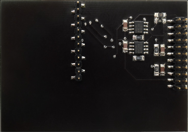
The output of the sensor is amplified using an instrumentation amplifier and filtered to prevent glitches caused by external magnetic fields.
Both outputs of the sensors are directly read with the Waspmote’s microprocessor’s analog-to-digital converter in
the analog input pins ANALOG1 and ANALOG7.
To read both outputs it is enough with executing the command readValue from the board’s library, in which the analog voltage
in the input of the analog-to-digital converter is captured.
It is convenient to wait for about two seconds after powering the sensor board and before reading the converter to assure
that the power supply voltage and the outputs of the sensors are all stable.
We have an example of code for reading the two sensors in section 3 of this manual.
